The beginner cyberdeck build runs on a USB power bank and a store-bought keyboard - good enough to prove the concept, not good enough to live with. This guide replaces both: a safe custom battery pack that outlasts a power bank and charges through the same port you already cut into the case, and a keyboard you wired yourself, so the layout is exactly the one your hands want. Both halves are independent - do one, the other, or both in one weekend.
Read this first: this guide handles lithium cells and live soldering. If you haven’t soldered a full project before, that’s fine - go build one first. Come back when this wouldn’t be your first rodeo.
Part 1: The battery pack
Step 1: Match your cells
Buy four 18650 cells from the same listing, same brand, same production batch - not four cells you happened to have in a drawer. Mismatched cells age at different rates once wired together, and the pack becomes only as good as its weakest cell. If you can’t spot-weld, pay the few extra dollars for cells with tabs pre-welded on; it removes the single riskiest step in this whole build.
Step 2: Insulate before you touch anything else
Before wiring, wrap a strip of fish paper or Kapton around each cell’s body, leaving only the two flat terminal ends exposed. The factory PVC wrap is thin, and once nickel strips are pressed against it, a single nick becomes a short circuit. This step takes ten minutes and it’s the one nobody regrets doing.
Step 3: Build the 4-cell string
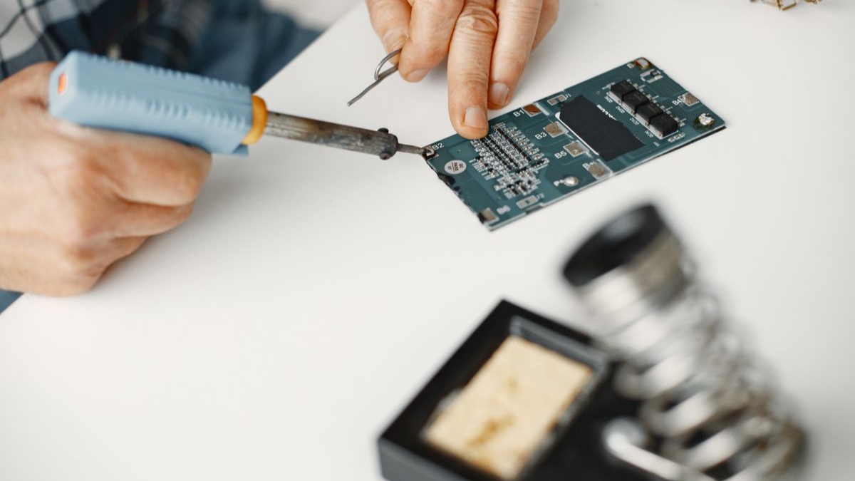
Seat the four cells in the plastic holder. Wire them in series for a 4S pack (four cells end to end, positive to negative, giving roughly 14.8V nominal, 16.8V fully charged) - this is the standard config a 4S BMS expects, so match your BMS purchase to this wiring. If using pre-tabbed cells, solder tab to tab in a quick pass, keeping iron contact under a few seconds per joint. If you’re spot-welding, follow your welder’s cell-to-strip settings exactly; overheating a cell here is the actual danger this guide keeps warning about.
Step 4: Wire in the BMS
Every lithium BMS board has labeled pads: B- (battery negative), B+ (battery positive, sometimes the pack’s main negative terminal - read your board’s diagram, they vary), and individual cell-tap wires (B1, B2, B3, B4) that connect between each cell in the string, not just the ends. This is what lets the BMS balance and protect each cell individually instead of just watching the pack as a whole. Follow your specific board’s diagram exactly - a skipped tap wire means a silently unprotected cell.
Step 5: Verify before you seal anything
With the BMS wired, set your multimeter to DC volts and check the pack’s output terminals: a freshly assembled 4S pack should read somewhere in the 14–17V range depending on charge state. Then check each individual cell’s voltage at its tap point - they should all sit within about 0.1V of each other. A cell that’s noticeably off is a problem to solve now, not after the case is closed.
Step 6: Add the 5V output stage
Wire the BMS’s protected output into a USB-C PD trigger board or a simple buck converter set to 5V - this is what actually feeds your Raspberry Pi, matching what the beginner guide’s power bank used to do. Bench-test it: multimeter on the 5V output pins, confirm a steady 5V before it ever sees the Pi.
Step 7: Mount and seal the pack
Tape or 3D-print a small tray for the cell holder and BMS board so nothing shifts or touches bare metal against the case. Route the charging port to a bulkhead connector on the case exterior - you want to plug in a charger without opening the deck. Close it up, charge it once fully while you’re in the room to watch, and confirm it charges to a stable, matched voltage across all four cells.
Part 2: The hand-wired keyboard
Step 8: Design your layout on paper first
Sketch the key layout you actually want - the beginner guide used a stock 60% keyboard; this is where you can go smaller, split, or rearrange keys to match your case’s real estate. Count your total keys and group them into a grid of rows and columns. A 4x12 grid (4 rows, 12 columns) comfortably covers a 48-key layout without wasting microcontroller pins.
Step 9: Wire the switch matrix
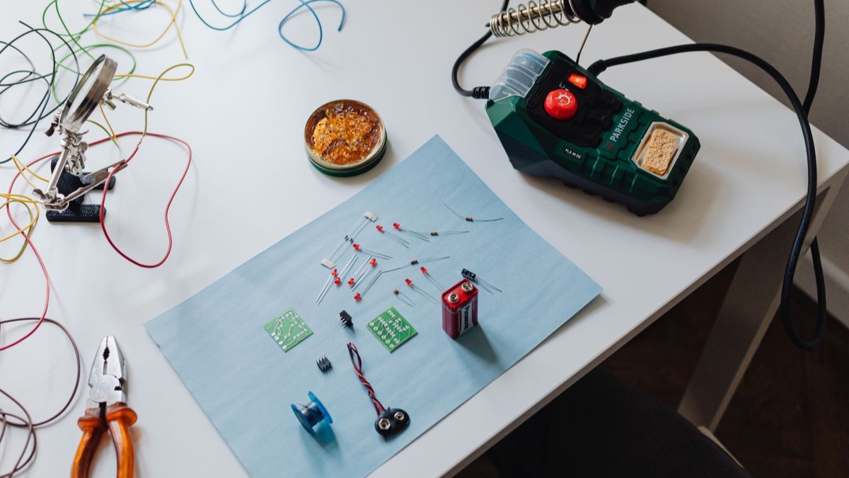
Place your switches into the plate or perfboard in your planned grid. On every single switch, solder a 1N4148 diode to one leg - the diode’s stripe (cathode) should all face the same direction across the whole board, this matters for the firmware step later. Solder diodes together in a line down each row. Solder the other switch leg together down each column. The diodes are what prevent “ghost” keypresses when you press multiple keys at once - skip them and multi-key combos will misbehave.
Step 10: Connect to the microcontroller
Run a wire from each row and each column to a separate pin on the Arduino Micro or Teensy. A 4x12 matrix needs 4 row pins + 12 column pins = 16 GPIO pins total, well within either board’s pin count. Keep a written map of exactly which physical wire goes to which pin - you’ll need it in the next step.
Step 11: Flash the firmware
Install QMK (or the simpler Arduino Keyboard library if you want to skip the QMK learning curve) on your second computer. In QMK’s config, define your pin map - which microcontroller pins are rows, which are columns - and your keymap - which physical switch produces which character. Flash it to the board. Plug the finished matrix into any computer over USB; it should show up as a standard keyboard with zero drivers needed.
Step 12: Strain-relieve everything
Before this keyboard goes anywhere near field use, hot-glue every solder joint and wire run against the plate. A hand-wired matrix is dozens of fragile joints, and a cyberdeck that travels will find every weak one. Five minutes of hot glue now saves a dead row of keys later.
Part 3: Bring it together
Step 13: Swap both into the deck
Pull the power bank and the store-bought keyboard from your existing build. Mount the battery tray where the power bank lived, wire its 5V output to the Pi exactly as the power bank did. Mount the new keyboard plate where the old one sat. Bench-test before closing the case: boot the Pi, confirm every key registers correctly, run it off battery alone for at least twenty minutes.
Step 14: Field test
Take it out and use it for the actual mission you defined in the beginner build. Time how long the new pack actually lasts under real use - write the number down, it’ll be higher than a power bank and it’s worth knowing exactly how much higher.
What worked and what didn’t
The first matrix build here had two diodes facing opposite directions in the same row - the firmware saw phantom keypresses on every third key until a single reversed diode was found and re-seated. Check your diode orientation twice before you solder the second one. On the battery side: skipping the individual cell-voltage check in Step 5 once let a slightly mismatched cell go unnoticed for a week, until the pack started reading oddly low. Five minutes with a multimeter would have caught it on day one.
The math
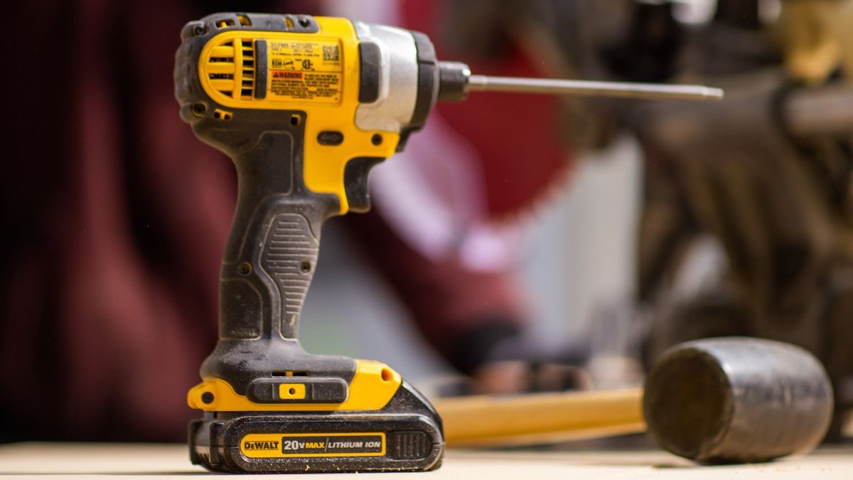
A quality USB-C power bank costs $35–50 and needs replacing every couple of years as its own internal cells degrade. A custom 4S pack costs about the same once and, because you built it, you can rebuild it exactly like the drill battery guide when a cell eventually weakens - same skill, same tools. A hand-wired keyboard costs roughly what a mid-range mechanical keyboard costs retail, except it’s built to your exact layout and you now know how to fix or rewire a dead key yourself instead of buying a replacement.